Large power cables create more than a weight problem: heat, bend radius, fault forces, vertical movement and access all affect the route. By the end, you will be able to compare ladder, perforated and solid-bottom trays, verify a tray’s real load requirement, and identify the installation details that prevent cable damage and magnetic heating.
Key takeaways
- Use ladder trays when large cables need easy placement and open access.
- Match ladder, perforated or solid-bottom trays to the route and cable environment.
- Calculate tray loading from cable sizes, weights and spacing in the cable schedule.
- Treat supports, bends and vertical restraints as one continuous load path.
Why the open ladder profile suits large power cables
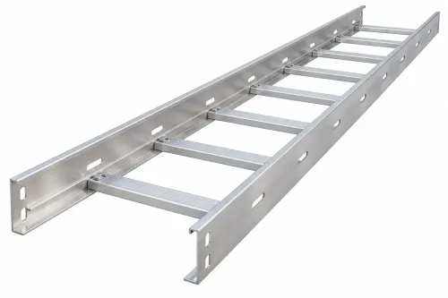
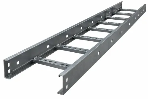
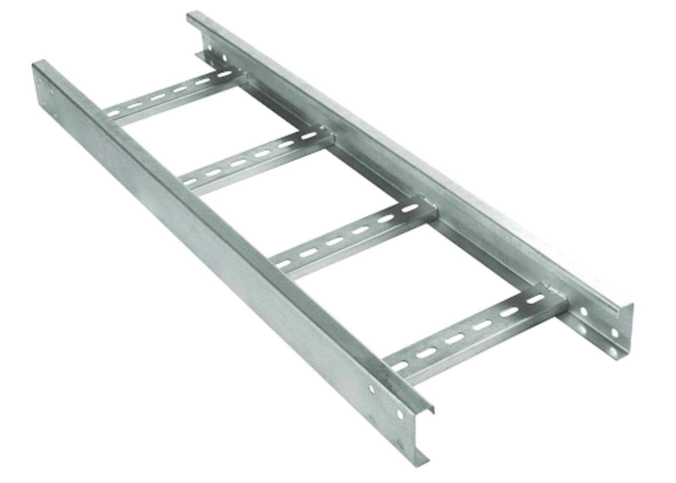
Large power cables are easier to place on a ladder cable tray because installers can set them onto the rungs instead of threading stiff lengths through a closed channel. That reduces handling strain where the cable’s minimum bend radius and pulling tension limit the route.
The open profile also improves heat dissipation by allowing air to circulate around the cable surface. It does not remove ampacity derating: conductor arrangement, grouping, ambient temperature and the applicable wiring rules still control allowable current. Keep single-core AC cables in the specified trefoil or spaced arrangement; nearby ferromagnetic steel can create unwanted heating.
Cable inspection access is another practical advantage. You can see the cable jacket, supports and identification along the route, then lift a cable clear for testing or replacement without dismantling a cover or pulling an entire bundle through a trough. Open rungs also give debris less continuous surface on which to collect.
For heavy-duty power cable distribution, confirm that the system—not just the tray section—matches the load and support span. NEMA VE 1 ratings include 50, 75, 100, 125 and 150 lb/ft at specified spans; a longer span reduces allowable capacity.
Rungs support placement, not fault restraint: single-core cables need cleats selected and spaced for prospective fault current under IEC 61914.
Ladder, perforated or solid-bottom: match the tray to the route
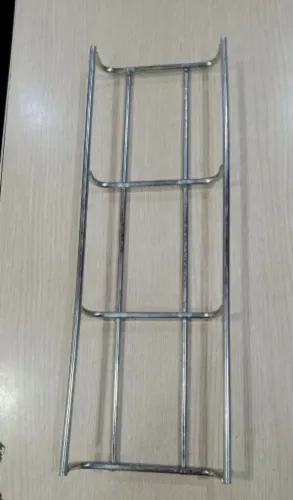
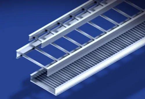
Ladder tray is the right choice for long runs of large, stiff power cables when access, cable ventilation and heat dissipation matter more than enclosure. Installers can place cables directly onto the rungs instead of pulling them through a closed channel, reducing handling difficulty where bend radius and pulling tension limit the route.
| Option | Main advantage | Choose it when | Avoid it when |
|---|---|---|---|
| Ladder tray | Maximum access and airflow | Large power cables, dry indoor routes, frequent inspection or replacement | Falling debris, wash-down water, corrosive deposits, fire exposure or unauthorised contact threaten the cables |
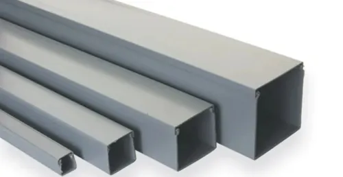
| Perforated cable tray | Continuous support with some airflow | Smaller cables, mixed services, moderate cable protection and separation, or routes needing a more contained base | The route needs strong exclusion of dust, water or chemicals |
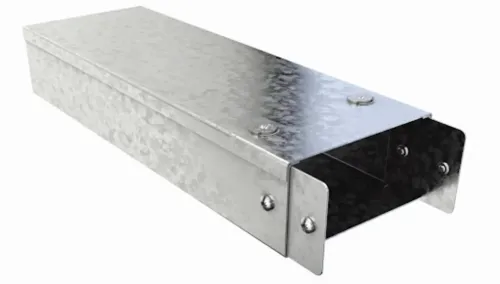
| Solid-bottom cable tray | Highest containment and continuous bearing surface | Cables need protection from dripping contaminants, loose material or objects entering from below | Heat removal, drainage, low weight or easy cable additions is important |
A cover can improve cable protection, but it adds weight and wind load; include both in the structural selection. A barrier or separate tray may also be better than relying on spacing when power, control and communication cables require defined cable protection and separation.
Compare installed system cost, not bare tray price. Covers, cleats, barriers, fire protection and extra support steel can erase ladder tray’s material saving. For single-conductor AC circuits, verify the specified cable arrangement, tray material and bonding details to control electromagnetic effects.
Verify tray capacity from the cable schedule, not the label
Start with the cable schedule, then test the tray against both space and load. A “heavy-duty” label does not confirm capacity for your route.
Record these inputs:
- Cable quantity, outside diameter and weight per metre
- Multiconductor or single-conductor construction
- Required phase arrangement, spacing and trefoil dimensions
- Planned additions, including their estimated size and weight
- Support span, bend locations and vertical sections
Tray fill is not interchangeable with conduit fill. The applicable wiring rules use different provisions for multiconductor and single-conductor cables, so do not select width by adding cable diameters alone. Include separation, rung spacing and the arrangement specified by the cable manufacturer.
Large single-core AC cables also need magnetic-effect control; nearby ferromagnetic plates or enclosure parts can create extra heating.
Complete a cable tray load calculation using the installed cable weight per metre, then add the reserved future load. Compare that result with the manufacturer’s rating for the actual support span and the specified NEMA VE 1 load class.
NEMA VE 1 ratings commonly use spans of 8, 12, 16 or 20 feet and distributed loads such as 50, 75, 100, 125 or 150 lb/ft. A longer span reduces allowable capacity.
Check allowable deflection, not only ultimate strength. Include covers, barriers, vertical cable weight, pulling forces and concentrated loads from maintenance activity. If the calculated load approaches the rating or deflection limit, reduce the support span or choose a stronger tray section.
Design the supports, bends and vertical runs as one load path
Treat the tray, brackets, splice plates and risers as one load path from the cable weight to the building structure. Cable tray support spacing controls allowable load and deflection: NEMA VE 1 ratings pair distributed loads such as 50, 75, 100, 125 or 150 lb/ft with defined spans from 8 to 20 ft.
Do not apply a short-span rating to a longer gap.
Cantilever brackets transfer bending and torsion into wall anchors, especially at bends and near tray ends. Check bracket deflection, anchor capacity and the rail’s local load at each support; a tray that passes a uniform-load check can still fail under a concentrated load.
Review these additional demands before fixing the spacing:
- Cable-pulling tension during installation
- A person, hoist or temporary equipment placed on the route
- Wind, ice or seismic forces on outdoor sections
- Covers, barriers and fittings added after the cable load is calculated
At a splice, use hardware that preserves rail alignment and the specified load capacity. Bond across the joint where electrical continuity is required. On long outdoor runs, expansion joints accommodate temperature movement; rigidly joining every section can load splice plates, supports and connected equipment.
A vertical cable tray needs its own restraint plan. Cable weight accumulates at bends, cleats and terminations, while rungs alone do not stop cables sliding downward. Add vertical clamps or cleats, maintain the manufacturer’s bend radius and transfer the accumulated load into supports designed for that direction.
Install power cables for restraint, fault safety and service life
Secure each cable to the tray, not merely on it. Ladder rungs support weight but are not a substitute for IEC 61914 cable cleats, which restrain single-core AC cables during a short-circuit fault.
Select cleats and spacing from prospective fault current, cable formation, fault duration and the cleat’s tested rating; ordinary tie-wraps do not provide that restraint.
Use this installation check before energising the route:
- Arrange single-core AC cables in trefoil or the specified spaced-phase formation. Keep ferromagnetic plates, glands and enclosures from surrounding individual conductors unless the design accounts for heating and circulating currents.
- Maintain the manufacturer’s minimum bend radius at every entry, exit, offset and termination. A sharp turn can damage insulation even when the cable appears undamaged.
- Add cleats or clamps for vertical sections and near bends and terminations. Cable weight accumulates at these points, so horizontal rung support alone cannot prevent movement.
- Bond tray sections across joints where continuity is interrupted, then connect the system to the protective earthing network. Inspect cable bonding after painting, cutting or installing covers.
- Specify corrosion protection for the environment and repair damaged coating at cuts, drilled holes and welds. Dissimilar metals and trapped moisture can accelerate corrosion at connections.
When assessing a route from S.V. Metals & Extrusions Pvt. Ltd., request the rail thickness, rung spacing, support-span load table and finish specification; these documents help verify restraint, bonding and corrosion protection rather than relying on a product label.
Related products
 | Cable Trays & Accessories Ladder Type Cable Trays are ideal for heavy duty power distribution in industrial facilities as it provides maximum ventilation and load carrying... View product → |
 | MS Painted Ladder Type Cable Trays ₹100 Our company is engaged in offering robust built Ladder Type Cable Trays that are made from the finest mild steel. View product → |
Frequently asked questions
Why are ladder cable trays suitable for large power cables?
Their open profile lets installers place stiff cables onto rungs instead of threading them through a closed channel, reducing handling strain around bend-radius and pulling-tension limits.
How do you choose between ladder, perforated and solid-bottom cable trays?
Choose the profile according to route conditions, cable support needs, ventilation, debris protection and access requirements rather than selecting by appearance alone.
How do you verify a cable tray’s capacity?
Use the cable schedule to calculate the installed cable weight, spacing and future allowance, then compare that load with the tray and support system’s rated capacity.
What must be considered when installing power cables on ladder trays?
Design tray supports, bends and vertical runs together, then secure cables against movement during installation, fault forces and long-term service.
Related products
 | MS Painted Ladder Type Cable Trays ₹115 We are offering MS Painted Ladder Type Cable Trays that are chiefly used for distribution of power and communication cables. View product → |
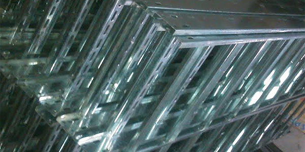 | Hot Dip Galvanized Ladder Type Cable Trays 113 Our company manufactures the finest range of Hot Dip Galvanized Ladder Type Cable Trays that is suited for heavy weight cables. View product → |
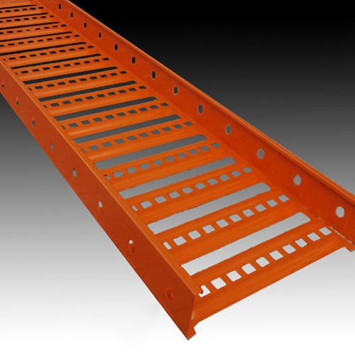 | Powder Coated Ladder Type Cable Trays 99 We are known for designing Powder Coated Ladder Type Cable Trays that are widely installed in industries, malls, railway stations, airports, office... View product → |
 | Pre Galvanized Ladder Type Cable Trays Features: 1)High weight bearing capacity 2)Used for reaching higher altitudes 3)Longer functional life 4)Excellent chemical resistance View product → |