The right tray depends on more than cable weight: route changes, bend radius, electromagnetic exposure, contamination, fire requirements and future additions all affect the decision. By the end, you will be able to identify suitable routes for wiremesh, set segregation and sizing rules, and reject it where protection or containment matters more than access.
Key takeaways
- Use wiremesh for accessible routes with frequent branches or future cable additions.
- Fit mesh liners, clips or covers when small cables could sag or fall through openings.
- Separate power from signal circuits using dedicated trays, spacing or grounded dividers.
- Choose ladder, perforated or covered trays for heavy, exposed or contamination-prone routes.
Which cable routes benefit most from wiremesh tray?
Choose wiremesh cable tray where the route changes after installation: branch-offs, equipment-room connections, tracing faults and adding cables are faster when you can see and reach the cable without pulling it through conduit. That practical advantage is strongest on short, accessible overhead runs and congested plant routes.
| Cable route | Practical advantage of open mesh | Check before choosing |
|---|---|---|
| Cat6A cable | Easy inspection, separation and additions; airflow helps avoid heat buildup in dense data routes | Preserve the manufacturer’s bend radius and prevent compression at bends |
| Fibre-optic cable | Quick visual tracing and access for testing or rerouting; electromagnetic coupling is not a concern | Control pulling tension, protect against crushing and keep sharp cut wires away |
| Shielded instrumentation pairs and control multicore cables | Branch connections and fault tracing are straightforward on accessible process or equipment routes | Open mesh is not an electromagnetic shield; retain cable screens and required distance from power |
Wiremesh cable tray suitability falls when the route is inaccessible, heavily congested or exposed to dropped objects, sunlight, rodents or unauthorized handling. A cover adds protection, but it does not create an enclosed conduit or excuse poor bend-radius control.
Inspect every field-cut section. Deburr it and fit edge protection where cables cross the cut mesh; an exposed wire end can abrade a thin data, fibre or instrumentation jacket. Also check that small cables cannot sag through openings, and size the tray for the complete cable weight rather than apparent spare space.
How do you keep small cables safe on an open mesh?
Use a support method that stops small-diameter cables from sagging into the openings, slipping beneath adjacent wires or rubbing against cut mesh ends. Open mesh improves cable ventilation and inspection, but it is not a substitute for mechanical support or grouping calculations.
- Fit a mesh liner, narrow cable-support strip or approved basket accessory where cable diameter is smaller than the openings. Protect every cut edge with an edge guard; a sharp wire can damage insulation during pulling or later movement.
- Set supports from the tray manufacturer’s span and load table, not from appearance. Check the complete installed weight, vertical runs, long spans and concentrated loads from junction boxes. Heavy control multicore cables can overload a span designed for data cables.
- Route each cable through bends without flattening the bundle. Check the cable manufacturer’s cable bend radius at elbows, tees and drops, then secure cables so ties do not crush them.
- Use the open structure for heat observation, not as permission to ignore ampacity rules. Check the cable manufacturer’s grouping and temperature limits for bundled communication cables, high-power PoE and control multicore cables.
- Leave measured spare width and install additional support points before the route fills. Add cables from accessible sides, keep them out of existing bend zones and do not drag new cables across exposed mesh ends.
Fit a cover where falling objects, sunlight, rodents or unauthorized handling threaten the route. A cover still does not provide conduit-level shielding, and it must preserve bend radius, ventilation and the tray’s rated loading.
How should data, instrumentation, control and power circuits be separated?
Insulation prevents contact; it does not prevent induced noise. Keep low-level circuits out of an undivided tray with high-noise circuits, especially where runs are long or heavily loaded.
Use one of these electromagnetic separation arrangements:
- A separate tray for analog, pulse, communication and safety-instrumented circuits
- A metallic divider arrangement tested for the cable types, loading and route length
- An engineered separation calculation that accounts for power-circuit current, loaded conductors, parallel-run length, cable screening and tray layout
Keep these noise sources out of the sensitive route:
- VFD output cables and motor feeders
- Welding circuits and other high-current power cables
An open wiremesh tray is not an electromagnetic shield. Its large apertures provide far less shielding than solid metallic tray or enclosed conduit, so do not rely on the mesh to replace screened cable, physical separation or a divider. A solid cover helps with containment but does not correct poor routing.
Use screened instrumentation and communication cables where the system design calls for them. Make the screen termination according to the equipment and EMC design; a long pigtail adds inductance, while high-frequency installations often require a short 360-degree bond at the gland or connector.
Do not assume that grounding one end suits every analog or safety circuit.
Where routes must cross, use a short 90-degree cable crossing. This limits the coupling length; running power and signal cables in parallel for metres is the more serious error. Crossing at 90 degrees reduces interference, but it does not replace required separation or screening.
When are ladder, perforated or covered trays the better choice?
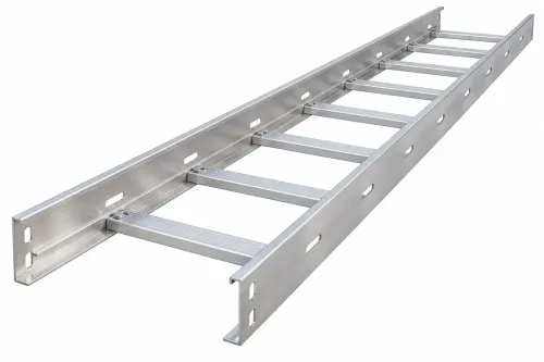
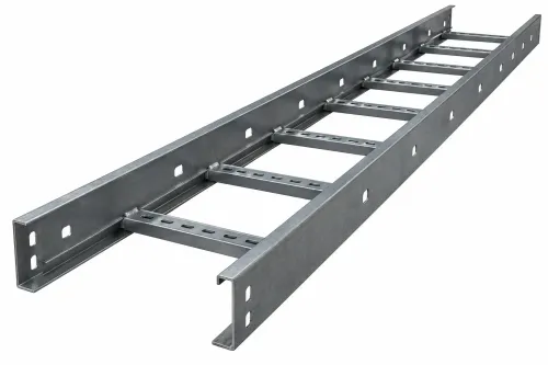
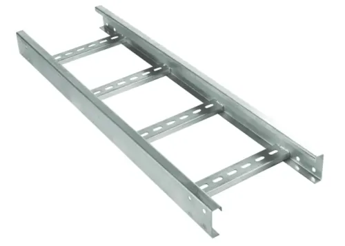
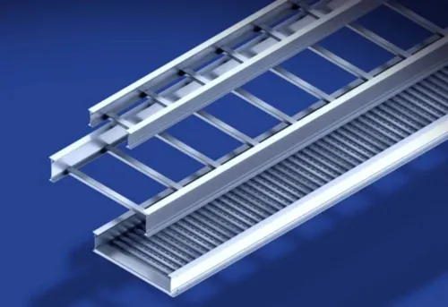
Use ladder trays for heavy, long-span loading; choose perforated or covered trays when cable protection matters more than rapid access. The right ladder cable tray comparison weighs load and span against falling objects, contamination and cable security, not price alone.
| Option | Loading and access | Protection and environment |
|---|---|---|
| Wiremesh | Suits light-to-moderate data, instrumentation and control loads, frequent additions and visual tracing | Least protection from impact, dust, rodents, sunlight and unauthorized handling; drains rain well but needs a corrosion-resistant finish outdoors |
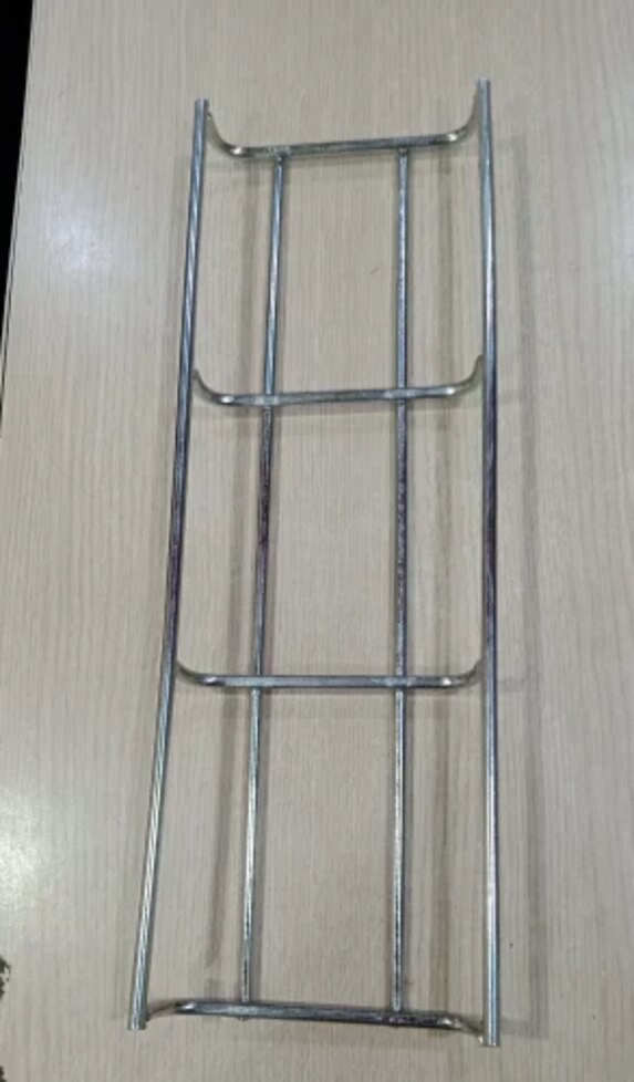
| Ladder | Carries heavier cables and longer spans with fewer supports; additions remain accessible | Open rungs leave small cables exposed and provide little dust or impact protection; use covers where outdoor debris or falling objects are a concern |
| Perforated | Offers a continuous base for smaller cables and moderate loading, with less access than mesh | Better mechanical support and containment than mesh, while retaining ventilation; the perforated cable tray comparison favours it where dust, abrasion or cable security is a concern |
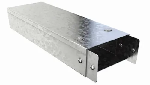
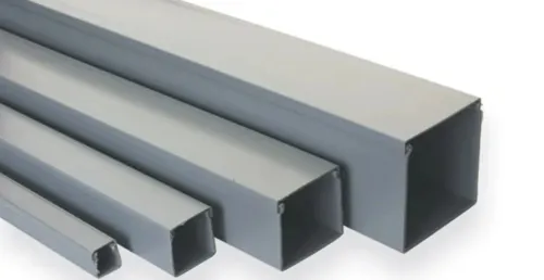
| Covered or solid-bottom | Handles routes needing a protected, contained cable path; additions and inspection take longer | Best against falling contamination, washdown, impact, rodents and sunlight; poorer heat dissipation, and water can collect if drainage is inadequate |
A cover does not create electromagnetic shielding equal to enclosed conduit, and no tray stops a fire crossing a wall or floor. Install a listed firestop system at each rated penetration.
In corrosive or coastal areas, specify a finish and hardware suited to the exposure, then verify joint continuity and bonding; do not assume the tray is the protective earth conductor.
What should you verify before specifying and ordering the tray system?
Turn the route drawing into a specification that states dimensions, tested performance and installation conditions—not merely “wiremesh tray.” Verify each point before ordering:
1. Measure the cable population at every straight, bend and branch. Specify tray width and depth from cable diameters, minimum bend radius and separation needs, then reserve spare capacity for planned additions without compressing bundles.
2. Select support spacing from the manufacturer’s span/load table. Check the complete installed cable weight, vertical runs, bends, covers and accessories; perform concentrated load calculations for junction boxes, drops and other equipment attached to the tray.
3. State the required material and finish for the environment: stainless steel grade for corrosive or hygienic areas, or a named galvanizing or paint system for indoor and outdoor exposure. Confirm cut-edge treatment and cover compatibility.
4. Require metallic continuity across every joint and bond the tray to the site earthing system where the governing code requires it. Do not count the tray as a protective earth conductor unless its construction, joints and manufacturer’s continuity data satisfy that code.
5. Mark every wall and floor penetration on the route. Order a compatible, listed firestop system for the barrier, cable types, tray arrangement, fill limit and annular space; the tray itself provides no firestop rating.
6. Ask S.V. Metals & Extrusions Pvt. Ltd. to confirm the quoted tray’s tested span, load, joint-bonding details and accessory limits against your schedule, rather than accepting a generic width-and-length quotation.
Related products
 | Cable Trays & Accessories Wire Mesh Cable Tray, also called Basket Cable Tray, is a kind of cable tray made of stainless steel wires by welding wires together, forming a... View product → |
 | Cable Trays & Accessories Wire Mesh Cable Tray Accessories Wire Mesh Cable Tray Accessories View product → |
Frequently asked questions
Which cable routes benefit most from wiremesh tray?
Wiremesh suits short, accessible overhead runs with frequent branch-offs, equipment-room connections, fault tracing and future cable additions.
How do you keep small cables safe on an open mesh?
Use suitable mesh liners, cable ties or clips, edge protection and covers where cables could sag, fall through openings or suffer damage.
How should data, instrumentation, control and power circuits be separated?
Use separate trays where practical, maintain the designed separation at parallel runs, cross at right angles, and add grounded dividers when circuits share a tray.
When are ladder, perforated or covered trays the better choice?
Choose ladder tray for heavy cables and long spans, perforated tray for continuous support and protection, and covered tray where dust, dripping water or falling objects threaten cables.
What should you verify before specifying and ordering a wiremesh tray system?
Confirm cable count, diameters, fill space, load, span, corrosion environment, bend fittings, supports, bonding, earthing, covers and route dimensions before ordering.