An MS ladder tray is suitable for heavy cable loads only when its capacity is proven for the actual span, cable arrangement, fittings and support system. By the end, you will be able to calculate the design load, identify local load risks, check installation conditions and prepare a procurement specification that separates a genuinely suitable tray from one labelled merely “heavy duty.”
Key takeaways
- Use the load-versus-span table for the exact tray and support arrangement.
- Add cable weight and concentrated forces to the design load.
- Check cable diameter, fill, spacing and thermal separation before choosing tray width.
- Specify steel grade, finish, supports, splices and electrical continuity together.
Start with the load-versus-span rating, not the words “heavy duty”
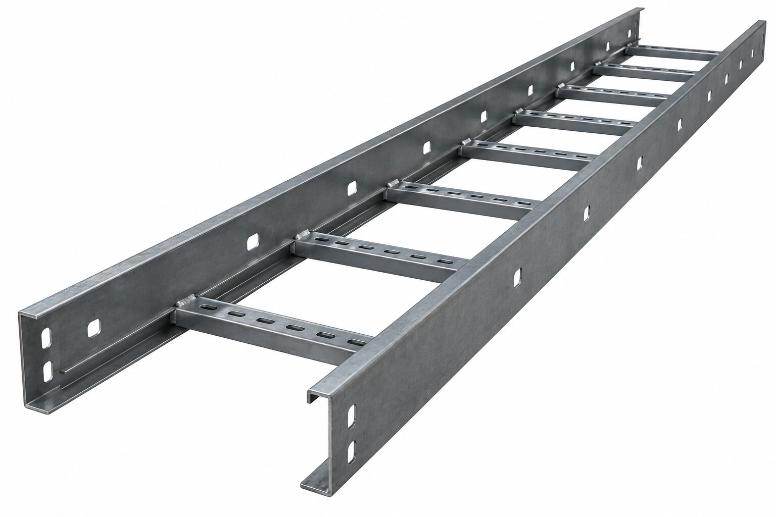
An MS ladder cable tray is suitable for heavy cable loads only when its allowable load at the specified support span exceeds the complete design load. Ask for a manufacturer’s load-versus-span table for the exact width, side-rail depth, steel thickness, rung design, splice arrangement and support layout—not a “heavy duty” label.
| Evidence to demand | What it must show | Reject it when |
|---|---|---|
| Load rating | Allowable uniformly distributed load in kg/m or kN/m at the project span, such as 1.5 m, 2.4 m or 3.0 m | The supplier gives only a load class or “industrial grade” |
| Deflection basis | Maximum mid-span deflection under the stated working load, plus the test method or calculation basis | No deflection limit or test basis is declared |
| Tray configuration | Width, rail height, rung spacing, material thickness, fittings and splice details used for the rating | The quoted section differs from the tested section |
| Support system | Bracket, trapeze, weld, fastener and anchor capacities for the full loaded span | Supports are rated only for the empty tray |
| Local forces | Maximum cleat load and a separate check for concentrated forces at bends, clamps, fittings and equipment entries | A uniform-load rating is presented as proof for every point load |
NEMA VE 1 load classes commonly run from 50 to 150 lb/ft with 4 to 12 ft spans; require both values in writing. Include cable, tray, fittings, covers, installation loads and applicable wind or seismic effects. A vertical run needs separate checks for cable cleats, vertical shear, pull-out and the lowest bend.
Calculate the cable load and check concentrated forces separately
Treat the straight tray and each force-transfer point as separate load cases. Calculate cable weight from the installed mass per metre, multiply by the supported length, then add tray, covers, separators, instrument tubing, accessories and the planned spare capacity.
Divide the continuously supported total by the span to obtain the uniformly distributed load in kg/m or kN/m.
Do not spread that result across a bend, tee, reducer, drop-out or equipment entry. If one cleat, clamp or fitting carries a cable bundle, model the transferred reaction as a point load and check the rung, side rails, splice, bracket and anchor at that location.
Use this checklist for each heavy-load location:
- Record the mass entering and leaving the fitting, including the length whose weight is transferred there.
- Calculate the cleat load from the cable weight above the cleat, cable spacing, friction or restraint, and any pulling or sliding force.
- Check the point load against the rung and fitting capacity; do not use only the straight-tray load table.
- For vertical runs, specify cleat spacing and check vertical shear, pull-out, support-frame reactions and the lowest bend.
- Add concentrated loads from covers, separators, expansion hardware and attached equipment separately from cable weight.
- Check brackets, trapezes, welds, fasteners and building anchors for the combined reaction, not the empty-tray mass.
A tray can pass its uniformly distributed load rating and still buckle at a rung, distort at a fitting or overload an equipment entry. Recalculate every change in cable grouping or support arrangement.
Match tray dimensions to cable size, fill and thermal separation
Start with the largest cable diameter and the required separation, then select the tray width rather than filling the nominal width edge to edge. For a single layer of power cables, add the cable outside diameters, specified gaps and clearance from each side rail; the remainder is usable tray area for future additions.
- Cable diameter sets the minimum tray width and affects whether cables can be cleated without crowding.
- Side-rail depth must provide structural stiffness and retain cables through bends, risers and vertical runs; a deeper rail does not automatically increase usable width.
- Rung spacing must suit the cable diameter, cleat footprint and support points. Wide-spaced rungs can leave smaller cables poorly supported.
- Cable fill must leave room for ventilation, installation and inspection. Do not treat the tray’s outside dimensions as available laying space.
Grouping changes the electrical result even when the steel tray carries the weight. Bundling several loaded circuits together reduces heat dissipation and can lower ampacity; calculate the allowable current using the applicable installation rules and IEC 60287 methods where required.
A ventilated ladder tray helps air movement, but it does not cancel grouping, ambient-temperature or solar-exposure derating.
Keep single-core AC cables in an arrangement that preserves thermal separation and use cleats rated for prospective short-circuit forces. Ordinary tie wraps do not control the electrodynamic movement of a fault. Choose the width and spacing from the installed cable layout, not from cable mass alone.
Design the supports, vertical transitions and electrical continuity as one system
Specify support spacing against the complete working load, not an empty-tray rating. Include:
- Cable, tray, cover, fitting, separator and instrument-tubing weight
- Installation and maintenance loads
- Wind or seismic effects where the project requires them
Rate cantilever brackets, trapeze supports, anchors, welds and fasteners for that same load case. Long spans reduce support count but increase bending and deflection, so place shorter spans near fittings, risers and splice locations; NEMA VE 2 provides guidance for support placement and fitting transitions.
A horizontal load table does not prove a vertical run is safe. Install vertical cable supports or cleats at calculated intervals, then check cable sliding, vertical shear, pull-out, frame capacity and the reaction at the lowest bend. A straight tray can pass its rating while the bend or cleat fails.
Outdoor and hot-process-area runs need movement provision. Use expansion splice plates with a calculated joint gap, and fit bonding jumpers that maintain continuity while the tray moves. Rigidly bridging every splice can push thermal forces into supports, fittings and equipment terminations.
Treat electrical continuity as a tested installation property, not a consequence of using steel. Verify continuity across splice plates, expansion joints, painted interfaces and field-cut sections against the project standard; install a separate protective bonding conductor where continuity cannot be demonstrated or the design requires one.
Specify steel, finish and supplier documents before placing the order
Before placing an order, make “MS” a complete specification. Mild steel cable tray is not a corrosion or capacity rating by itself; two trays labelled heavy duty can differ in thickness, span performance and finish.
1. Request the declared or tested standard, including NEMA VE 1 where specified, plus a drawing showing tray width, side-rail height, rung spacing, steel grade and thickness.
2. Request a load table stating allowable load in kg/m or kN/m for your exact tray size and support span. Include the working-load deflection limit, test method or calculation basis, fitting derating, maximum cleat load and the assumed support, anchor and fastener arrangement.
3. Request the complete load case: tray and cable weights, fittings, covers, installation or maintenance loads, and seismic or wind forces where applicable. Confirm that brackets, trapezes, welds, anchors and building attachments are rated for the same case.
4. Specify corrosion protection by environment, not by the word “galvanized.” State the corrosion category, coating mass or thickness, surface preparation and approved repair method for cut edges and drilled holes. Hot-dip galvanizing after fabrication is different from pre-galvanized sheet; identify requirements for field damage and dissimilar-metal contact.
5. Obtain splice, expansion-joint and bonding details, including continuity testing and any separate protective bonding conductor. Ask for installation drawings and confirm that cable spacing, ambient temperature and solar exposure align with the project’s ampacity calculation, including IEC 60287 where used.
S.V. Metals & Extrusions Pvt. Ltd. can receive this schedule as part of an enquiry, giving its quotation a defined technical basis rather than an uncheckable “heavy duty” label.
Related products
 | Cable Trays & Accessories Ladder Type Cable Trays are ideal for heavy duty power distribution in industrial facilities as it provides maximum ventilation and load carrying... View product → |
 | MS Painted Ladder Type Cable Trays ₹100 Our company is engaged in offering robust built Ladder Type Cable Trays that are made from the finest mild steel. View product → |
Frequently asked questions
How do you know whether an MS ladder cable tray can carry heavy loads?
Compare the complete design load with the manufacturer’s allowable load at the specified support span for the exact tray configuration.
What loads must you calculate for a ladder cable tray?
Calculate the combined weight of all cables and assess concentrated forces separately, including loads at bends, vertical transitions and pulling points.
How should tray dimensions be selected for large cables?
Check cable diameter, fill, spacing and thermal separation, then select a width and side-rail depth that accommodate installation and heat dissipation.
What should be specified before ordering an MS ladder cable tray?
Specify steel and thickness, surface finish, tray dimensions, support spacing, splice details, earthing provisions and required supplier documents.
Related products
 | MS Painted Ladder Type Cable Trays ₹115 We are offering MS Painted Ladder Type Cable Trays that are chiefly used for distribution of power and communication cables. View product → |
 | Hot Dip Galvanized Ladder Type Cable Trays 113 Our company manufactures the finest range of Hot Dip Galvanized Ladder Type Cable Trays that is suited for heavy weight cables. View product → |
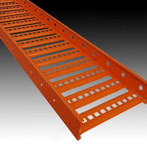 | Powder Coated Ladder Type Cable Trays 99 We are known for designing Powder Coated Ladder Type Cable Trays that are widely installed in industries, malls, railway stations, airports, office... View product → |
 | Pre Galvanized Ladder Type Cable Trays Features: 1)High weight bearing capacity 2)Used for reaching higher altitudes 3)Longer functional life 4)Excellent chemical resistance View product → |