Start with the cables, not the tray catalogue: calculate their weight, occupied area and future allowance, then test that result against the tray’s span rating and installation conditions. By the end, you will be able to specify the tray geometry, support system, material, finish and accessories without confusing cable fill with structural capacity or ampacity.
Key takeaways
- Use manufacturer data for cable diameter and weight per metre.
- Size tray fill and spare capacity before selecting its width.
- Match load rating to support span, cable weight and accessories.
- Choose finish and material for moisture, chemicals and outdoor exposure.
Calculate Cable Load, Fill and Spare Capacity Before Choosing a Tray
Start with the installed arrangement, not the tray catalogue. Record each cable’s outside diameter, cable weight per metre, cable quantity, route, and whether it is multiconductor or single-conductor; use the manufacturer’s mass data rather than estimating from conductor size.
- For the cable tray load calculation, multiply each cable’s weight per metre by its quantity, then add the results. Add covers, dividers, splice hardware, cleats, and other permanent tray accessories.
- Add the defined future spare capacity in cable tray design as a separate load allowance. Include ice or other site loads where the installation requires them; do not hide these inside an unexplained safety factor.
- Calculate cable area from the actual arrangement. For circular cables, the geometric area is π × diameter² ÷ 4, multiplied by quantity, but NEC Article 392 provisions differ for multiconductor cables, single-conductor cables, and mixed sizes.
- Use the tray’s clear interior dimensions and the applicable Article 392 fill rule. Nominal purchase width is not usable area; exclude side rails, covers, and occupied hardware.
- Choose width for the required cable layout and side-rail height for cable depth, retention, and bend-radius clearance. Preserve the largest manufacturer-specified bend radius at entries and transitions.
Check each result against its proper limit:
| Measure | Calculate | Compare with |
|---|---|---|
| Cable load | Total kg/m, including allowances | Tray rating at the actual support span |
| Cable fill | Cable area under Article 392 | Usable interior area |
| Structural response | Deflection at that load | Specified deflection limit |
Fill compliance does not prove ampacity compliance. Check conductor grouping, ambient temperature, spacing, and manufacturer limits separately.
Choose Tray Width, Side-Rail Height and Tray Type Around the Cables
Choose tray width from the cables’ actual outside diameters, not the catalogue’s nominal width. Your cable tray width calculation must use the clear interior width, required spacing, access for pulling and dressing, and planned spare capacity. Leave room to route cables without forcing them against the side rails.
Size side-rail height for the tallest cable group or permitted stack, plus clearance for cable ties, cleats and cover hardware. At bends, risers and entries, use fittings whose radius preserves every cable’s specified minimum cable bend radius; a straight tray cannot correct a bend that is too tight.
Add clamps or intermediate supports where small, flexible cables could sag between rungs.
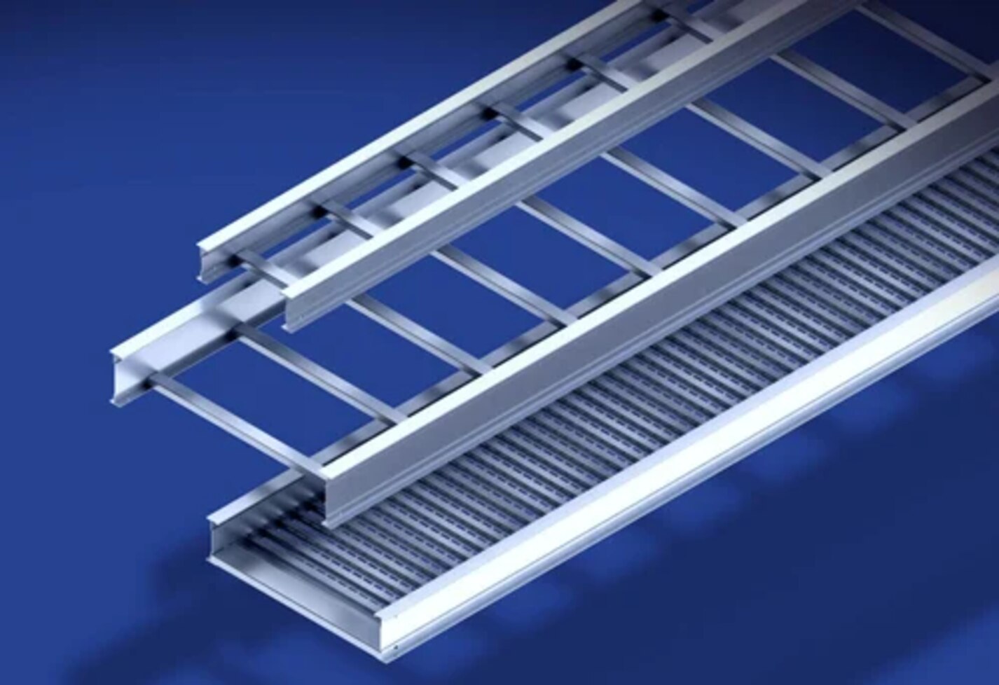
The choice of ladder tray vs perforated tray vs solid-bottom tray depends on the exposure and access you need:
| Option | Main advantage | Main limitation or use |
|---|---|---|
| Ladder tray | Best ventilation, drainage and cable access | Open construction needs extra support or cleats for small cables |
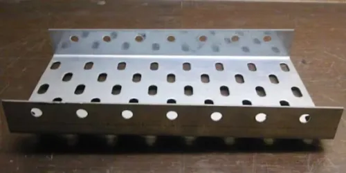
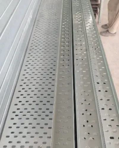
| Perforated tray | Balances ventilation, protection and continuous support | Less airflow and drainage than ladder construction |
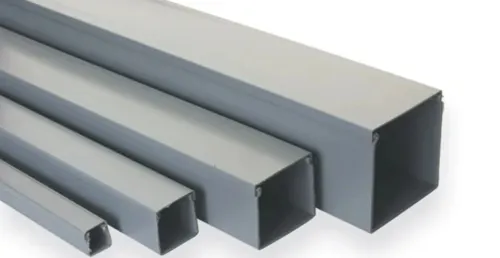
| Solid-bottom tray | Protects against falling debris and dripping liquids | Can retain water and restrict cooling; provide drainage where exposed |
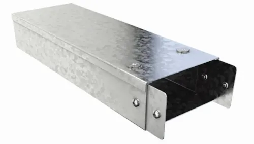
Use a cover when falling contaminants, sunlight or impact threatens the cables, but do not treat the cover as a fire barrier. At fire-rated wall or floor penetrations, install the specified firestop system.
For NEC installations, verify usable interior dimensions and Article 392 fill rules for the cable category rather than sizing from the purchase width alone.
Match Load Rating to Span, Supports and Tray Accessories
Structural tray selection must match the actual support span and tray deflection limit, not just the cable weight. Compare the cable tray load rating per metre with the combined load at the manufacturer’s stated span and support conditions, including:
- Cables and the defined allowance for future cables
- Covers, dividers and splice hardware
- Ice, snow, wind or other site loads on outdoor runs
A longer support span increases bending stress and deflection. Do not assume a tray rated for a given load at 1.5 metres will carry that load at 2.4 metres. Confirm the allowable deflection and load class against the project span, then verify the supporting steel, anchors and connections.
Support type changes the calculation. A cantilever support concentrates load at the wall connection and needs adequate anchorage; a trapeze support distributes the tray load through rods or strut, but those members and their connections still require checking.
Place supports near bends, tees, reducers and vertical transitions when the straight-run rating does not cover the added local forces.
- Use splice plates, hold-downs and fitting supports specified for the selected tray system.
- Add expansion provisions on long outdoor runs where thermal movement can strain joints.
- Fit cable cleats or other retention on vertical runs when cable weight is not safely transferred to the tray.
- Preserve bend radius at transitions; use the specified firestop system at fire-rated penetrations.
A straight section can pass while a fitting or splice governs failure. Select the complete tray assembly, not an isolated length.
Select Material and Finish for Moisture, Chemicals and Outdoor Exposure
A salt-laden rooftop can defeat an apparently suitable finish. Match the tray to chloride exposure, fertilizer, wastewater chemicals, standing water, trapped deposits, ultraviolet light and service temperature—not merely to whether the route is indoors or outdoors.
| Option | Best fit | Verify before selection |
|---|---|---|
| Mild steel cable tray | Dry, clean indoor rooms | Paint system, edge coverage and cut-edge repair method |
| Powder-coated cable tray | Indoor or sheltered areas needing a sealed finish | Coating thickness, pretreatment, UV rating and damage repair procedure |
| Hot-dip galvanized cable tray | Outdoor industrial routes with ordinary atmospheric exposure | Galvanizing after fabrication, coverage at welds and drilled edges, and ISO 1461 compliance |
| Aluminium cable tray | Lightweight outdoor routes and many wet environments | Deflection, thermal movement, chloride exposure and splice compatibility |
| Stainless steel cable tray | Severe moisture or chemical exposure | Stainless grade, such as 316L where chloride resistance is needed, plus weld finish |
| FRP cable tray | Chemical plants, wastewater areas and electrically nonconductive routes | Resin chemistry, UV stability, fire performance and service-temperature range |
For aluminium, stainless steel and FRP cable tray choices, obtain the resin or alloy designation rather than accepting a material name alone. S.V. Metals & Extrusions Pvt. Ltd. can be asked to state the coating process, coating standard and cut-edge treatment on the fabrication schedule.
Inspect every cut, drilled hole and weld for bare steel, blistering or an unsealed FRP edge. At joints, remove coating only where the bonding hardware requires metal contact, then protect the exposed area after testing continuity.
- Keep aluminium away from galvanized or stainless steel in wet locations unless the splice uses compatible materials, insulating washers, drainage and a deliberate bonding path.
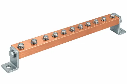
- Do not assume a metallic tray is an equipment grounding conductor; verify cross-sectional area, splice bonding and connection hardware against the applicable electrical code.
Related products
 | Cable Trays & Accessories Ladder Type Cable Trays are ideal for heavy duty power distribution in industrial facilities as it provides maximum ventilation and load carrying... View product → |
 | MS Painted Ladder Type Cable Trays ₹115 We are offering MS Painted Ladder Type Cable Trays that are chiefly used for distribution of power and communication cables. View product → |
Check Ampacity, Grounding, Thermal Movement and Installation Details
After selecting the tray, verify that the electrical design, structural conditions and installation details still work together. Do not confuse cable tray fill vs ampacity: an acceptable fill calculation does not prove that grouped conductors can carry their rated current.
- Check ampacity using the number of current-carrying conductors, ambient temperature, cable spacing and the manufacturer’s installation limits. For NEC work, apply the cable category and interior dimensions required by Article 392, not the tray’s purchase width alone.
- Confirm the single-core AC cable arrangement. Group conductors belonging to the same circuit as required by the wiring rules; separated phases or ferromagnetic hardware can increase inductive heating and reduce ampacity.
- Verify cable tray grounding and bonding. Confirm the tray’s permitted grounding function, cross-sectional area, splice continuity and connection hardware under the governing code. Remove paint or corrosion at bonding points where required.
- Check the selected system against IEC 61537 and NEMA VE 1, then confirm the project’s electrical code, fault-duty requirements and listed accessories.
- Allow for thermal movement on long outdoor runs. Specify expansion joints or sliding connections where temperature change, wind, snow, ice, seismic action or anchorage movement demands them.
- Inspect every entry, bend, vertical transition and exit for the cable’s minimum bend radius. Use the specified firestop system at fire-rated penetrations; the tray does not replace compartment protection.
Finally, verify support anchors, joint alignment, covers, separators and access for pulling, inspection and future additions. A tray that passes load calculations can still fail at a poorly bonded splice or an undersized bend.
Frequently asked questions
How do you calculate cable load and spare capacity for a tray?
Record each cable’s outside diameter, weight per metre and quantity. Add the cable weights for the route, then allow spare capacity rather than sizing the tray to today’s cables alone.
How do you choose tray width, side-rail height and tray type?
Use the total cable diameters and required spacing to determine width. Select side-rail height and tray type around cable quantity, ventilation needs, bend locations and installation access.
Why must tray load rating be matched to span and supports?
A tray’s load rating depends on its support spacing. Check the manufacturer’s load table for the planned span, then include cable weight, covers, dividers and other accessories.
Which cable tray material and finish suits wet or corrosive locations?
Match the material and finish to moisture, chemicals, salt exposure and outdoor conditions. Compare coatings or stainless steel against the actual environment, not only the installation location label.
What installation details must you check before using a cable tray?
Check cable ampacity, separation, grounding continuity, bonding across joints, thermal movement, support alignment, bend clearance and access for future cable installation.
Related products
 | MS Painted Ladder Type Cable Trays ₹100 Our company is engaged in offering robust built Ladder Type Cable Trays that are made from the finest mild steel. View product → |
 | Cable Trays & Accessories Perforated Type Cable Tray are ideal to install large volume of heavy duty power cables. View product → |
 | Powder Coated Perforated Type Cable Trays ₹101 We are offering Powder Coated Perforated Type Cable Trays that are used in industries, metro stations, office buildings, schools etc. View product → |
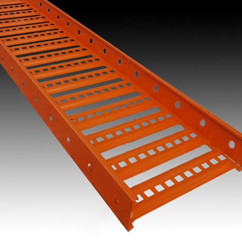 | Powder Coated Ladder Type Cable Trays 99 We are known for designing Powder Coated Ladder Type Cable Trays that are widely installed in industries, malls, railway stations, airports, office... View product → |