
Cables fail in raceways when impact, dust, movement, heat, interference, poor filling, or an unsuitable fitting is treated as an afterthought. By the end, you will be able to match the cable route to the environment, calculate usable capacity, specify segregation, and check the installation details that protect both cables and signals.
Key takeaways
- Use raceway to support cables, reduce incidental impact, and control route changes.
- Match tray, ladder, or enclosed raceway formats to cable type and environment.
- Size for cable fill, bend radius, separation, access, and future additions.
- Specify material, fittings, supports, bonding, covers, and installation checks.
What protection does a pre-galvanized raceway provide?
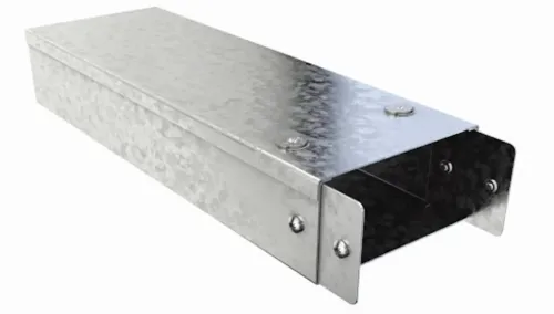
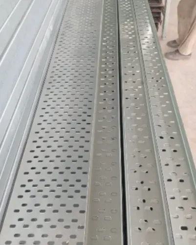
A pre-galvanized raceway protects cables by giving them a supported, defined route instead of leaving them exposed. Its steel base and sidewalls reduce incidental impact, prevent cables from sagging or shifting, and help block accidental contact with nearby tools, materials, or personnel. Fittings keep changes in direction controlled.
It provides:
- Impact protection from routine knocks and handling around the cable route.
- Cable protection against abrasion caused by unsupported movement or contact with rough structural surfaces.
- Dust protection against falling or settling debris when the raceway has a suitable cover, though it is not automatically dust-tight.
The route still needs correct sizing, supports, dividers, and fittings. A tight elbow, reducer, tee, or vertical transition can damage insulation if it violates the cable manufacturer’s minimum bend radius or lets cable weight bear on a sharp edge.
Mixing power and control cables in one route can also create electromagnetic interference even when they physically fit.
Protection stops where the raceway is not designed for the hazard. Open or covered raceway is not a watertight enclosure and will not reliably stop washdown, conductive dust, rodents, fire exposure, or falling heavy objects; use solid-bottom trunking, conduit, or a listed enclosure when those risks apply.
Pre-galvanized steel also loses its original zinc protection at cut edges, drilled holes, welds, and badly abraded areas, so those locations need specified corrosion treatment.
Which raceway format suits each cable and environment?
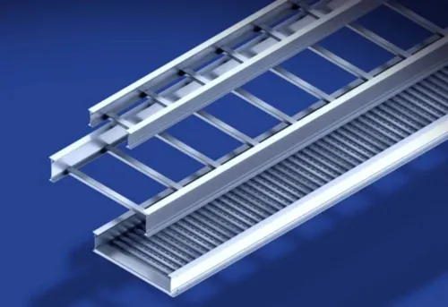
Choose the format by exposure, cable sensitivity and heat dissipation—not by empty tray volume alone. These raceway types fit different jobs:
| Option | Best fit | When it applies |
|---|---|---|
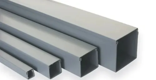
| Enclosed raceway | Data cables, telecommunications cables and small control cables | Use for a defined, protected route where accidental contact, light impact or visual containment matters; do not assume it is watertight or dust-tight. |
| Solid-bottom trunking | Control cables, shielded instrumentation cables and low-voltage data cables | Choose it where falling debris, conductive dust or cable movement threatens delicate circuits. Add a properly specified cover when the environment demands more protection. |
| Perforated cable tray | Control cables, instrumentation cables and moderate power cables | Use it for ventilated indoor routes and accessible branching. Keep power and sensitive signals separated with spacing, dividers or a documented EMC design. |
| Ladder tray | Large power cables and heavy feeder routes | Choose it for high heat dissipation, long straight runs and easy cable access. It offers less physical protection from falling objects and contamination. |
Do not mix power cables with control cables, shielded instrumentation cables, data cables or telecommunications cables merely because they fit. Variable-frequency-drive outputs and high-current feeders can disrupt low-level analogue and communications circuits; use separate trays or metallic dividers when the installation design requires them.
For washdown, rodents, fire exposure or conductive dust, select covered trunking, conduit or a listed enclosure instead of relying on an open tray. Confirm cable fill, bend radius, support load and outdoor ampacity separately.
How do you size the raceway and keep cable systems separated?
Size the raceway from the code-permitted cable fill, then reserve spare capacity for future cables. A cable fill calculation adds the cross-sectional area of each cable and compares the total with the allowable fill for its cable type and arrangement under the governing code; it does not use the raceway’s empty geometric volume alone.
NEC Article 392, for example, treats multiconductor, single-conductor, control and signal cables differently.
Check these dimensions before selecting the section:
- Preserve the largest manufacturer-stated bend radius at every elbow, tee, reducer and vertical transition. A straight run with adequate cable fill still fails if a fitting forces a tighter curve or lets cable weight bear on a sharp edge.
- Keep cover clearance above the cable bundle so the cover does not crush insulation, obstruct heat dissipation or prevent future cables from being installed.
- Specify a documented reserve for future cables rather than filling the raceway to its permitted limit on day one. Recheck ampacity where outdoor heat, solar gain, grouping or a cover reduces cooling.
- Use internal partitions, separate trays or physical spacing for cable segregation. Keep high-current feeders and variable-frequency-drive output cables away from low-level analogue, instrumentation, safety, data and communications circuits.
| Circuit type | Preferred separation approach | Main EMI concern |
|---|---|---|
| Power and VFD | Separate route or bonded metallic divider | Electromagnetic interference from switching and high current |
| Control and analogue | Separate compartment; use shielded cable where specified | Noise on low-level signals |
| Data and communications | Separate route or partition; follow cable-system requirements | Packet errors and communication loss |
| Safety circuits | Dedicated segregation defined by the project design | A fault or noise event disabling protection |
Which installation details determine whether the route works?
Set support spacing and span spacing from the manufacturer’s tested configuration, not from appearance. A tray load rating applies to a stated span, load distribution, splice location and orientation; check NEMA VE 1 or IEC 61537 data before extending spans or placing concentrated equipment.
Include cable weight, future capacity and cable ampacity checks, since a crowded route can overheat even when the steel does not deflect.
Verify these installation points before delivery:
- Supports must keep the raceway level, prevent twisting and leave access for couplers. Do not let a splice hang unsupported.
- Bends, tees, reducers and vertical transitions must preserve the cable manufacturer’s minimum bend radius and pulling limit. A sharp edge can damage insulation under tension.
- Covers and end caps must fit the selected section, remain secure under vibration and not obstruct heat dissipation or drainage.
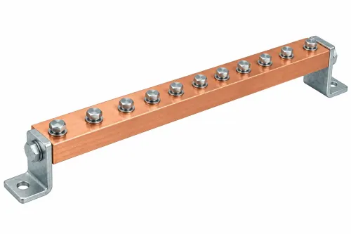
- Bonding jumpers and protective-earthing connections must maintain equipotential bonding across every joint. Zinc coating alone does not guarantee continuity.
| Check | Verify before installation | What goes wrong if missed |
|---|---|---|
| Field work | Deburr drilled holes and cuts; apply the specified zinc-rich repair coating at the required dry-film thickness | Exposed steel rusts and sharp edges damage cables |
| Moisture | Provide drainage and ventilation; separate wet-stacked sections | White rust returns when trapped condensation remains |
| Environment | Assess chlorides, acidic condensate, alkaline chemicals, treated timber and dissimilar metals | Coating loss or galvanic corrosion can shorten service life; select heavier coating, paint, stainless steel or nonmetallic raceway |
How do you turn the cable-route decision into a project specification?
State the raceway specification as a measurable schedule, not “galvanized steel.” Record material grade, dimensions, wall thickness, cover and fittings, finish, splice design, support spacing, bonding method, and the project design code governing cable separation, earthing and ampacity.
- Name the galvanized coating grade: ASTM A653 G60 or ASTM A653 G90. The designation expresses total zinc coating mass on both sheet surfaces; ASTM A653 G90 is approximately 275 g/m² total, not a guaranteed 20-micrometre thickness on each side.
- Attach cable schedules, route drawings, bend-radius requirements, spare capacity, environmental exposure, support spans and load data. Include covers, separators, expansion joints and the permitted installation orientation.
- Specify field-cut protection: remove burrs, clean the steel, and apply a compatible zinc-rich repair coating using the stated preparation and minimum dry-film thickness.
- Require continuity checks, bonding jumpers and protective-earthing connections where the design uses the metallic route for bonding or screening.
| Item | Manufacturer support | Project engineer’s check |
|---|---|---|
| Coating and material selection | Provide certificates, dimensions, finish details and manufacturer data | Confirm the galvanized coating grade, corrosion exposure and project design code |
| Capacity and strength | Supply tested load ratings and span limits | Recalculate cable fill, deflection, bend space and concentrated loads |
| Installation | Provide approved fittings, splice details and field-cut repair instructions | Approve routing, supports, ampacity, separation and site conditions |
S.V. Metals & Extrusions Pvt. Ltd. can convert the approved schedule into drawings, cut lists and fabrication details, but those documents do not replace the engineer’s design checks or site inspection.
Related products
 | Pre- Galvanized Raceways Raceways ₹121 Our company develops supreme quality Raceways that are widely installed in distribution of power cables throughout building premises. |
 | Pre Galvanized Perforated Type Cable Trays ₹99 Pre Galvanized Perforated Type Cable Trays are widely used for power circulation in residential buildings, commercial complexes, institutes,... View product → |
Frequently asked questions
What protection does a pre-galvanized raceway provide?
It gives cables a defined, supported route that reduces sagging, shifting, incidental impact, and accidental contact with nearby tools or materials.
Which raceway format suits each cable and environment?
Choose an open tray or ladder format when ventilation and access matter; choose an enclosed raceway when cables need greater protection from dust, impact, or contact.
How do you size the raceway and keep cable systems separated?
Allow space for cable fill, bend radius, supports, heat dissipation, and future additions, then separate power, control, instrumentation, and communications cables as the design requires.
Which installation details determine whether the route works?
Check support spacing, bend fittings, edge protection, covers, bonding continuity, entry points, access for maintenance, and clearance from heat or mechanical hazards.
How do you turn the cable-route decision into a project specification?
State the raceway format, steel finish, dimensions, cable groups, fill limit, fittings, supports, covers, bonding method, environmental exposure, and inspection requirements.