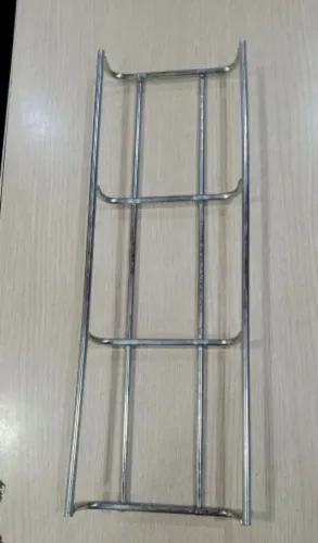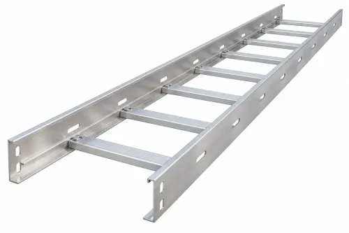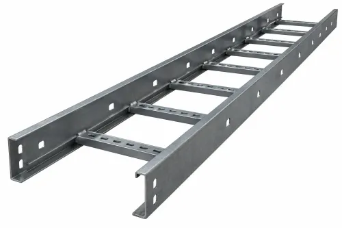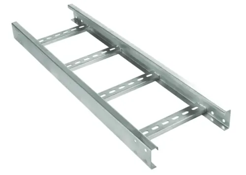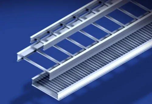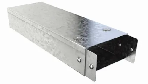
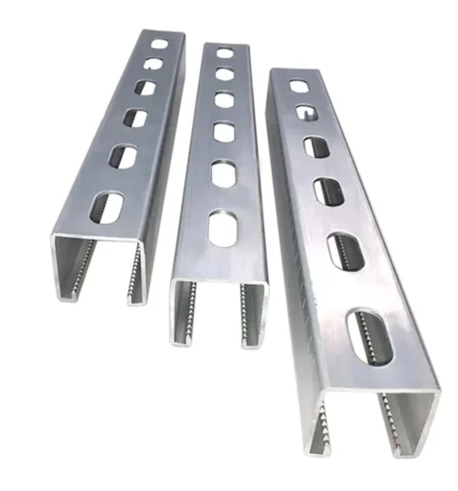
A cable tray does not hang from empty space: its weight reaches the building through a chain of channels, brackets, rods, clamps, anchors and fasteners. You will be able to identify that load path, choose a suitable channel assembly, verify support locations and avoid installation details that reduce capacity or compromise grounding.
Key takeaways
- Use channel depth and thickness to control stiffness and slot deformation.
- Transfer tray loads through brackets, anchors and building structure—not just the channel.
- Check tray weight, cable load and support spacing before selecting the channel.
- Choose finish and material for moisture, chemicals, temperature and corrosion exposure.
What a slotted C channel does beneath a cable tray
Beneath a cable tray, a slotted C channel is a rolled steel profile with a continuous longitudinal slot, two flanges and a web. Channel dimensions and orientation determine the arrangement: greater width gives more bearing and fixing space, greater depth improves stiffness but consumes clearance, and greater thickness increases resistance to bending and slot deformation.
Turning the flanges inward or outward changes nut access, tray bearing and obstruction risk.
Use this channel for a trapeze, wall bracket or equipment frame—not as a C-channel cable tray that directly carries cables. The tray remains responsible for its side rails, rungs, splice plates, covers and load rating. Check the channel and tray as one installation.
Common support arrangements include:
- A horizontal channel fixed to two threaded-rod hangers beneath the structure.
- A wall-mounted channel secured through brackets or anchors, with the tray attached to its face.
- A cantilever arm fixed to a vertical channel, supporting the tray from one side.
Keep every support outside the cable’s required path. Check the cable manufacturer’s minimum bend radius at bends, risers and entries, then reserve installation clearance around the channel flange, threaded rod and tray fittings. A narrow trapeze or misplaced rod can block the bend envelope even when the tray width and vertical load appear adequate.
Check these points before loading cables:
- Confirm the tray hardware bears fully on the channel.
- Confirm channel nuts and washers match the slot and load direction.
- Confirm no flange or rod intrudes into the cable bend zone.
How the support assembly transfers load into the building
The load reaches the building through every connection between the tray and structure, so survey the route before selecting hardware. A strong channel cannot compensate for an unsuitable anchor, clamp, rod or bracket.
1. Locate beams, concrete zones, embedded steel, obstructions, fire-rated penetrations and the intended tray route. Record edge distances, access for drilling, clearance for cable bends and any point where the route must change.
2. Select anchor points for the actual structure. Use beam clamps on suitable steel members, or anchors and threaded rods sized for the concrete condition and direction of loading. Do not assume a published rating applies when bolt size, edge distance or anchor condition differs.
3. Attach channel brackets, cantilever arms, channel nuts or spring nuts, washers and tray-to-channel hardware. The rods, nuts, washers, clamps, anchors and brackets all carry the load; the complete assembly is limited by its weakest component.
4. Set the channel and tray level before final tightening. Check that the rods are plumb, edge distances remain adequate and tray joints align. An offset tray or one-sided cable loading can twist a trapeze and create unequal rod reactions.
5. Tighten each connection to the hardware maker’s specified torque. Inspect for loose or rotated channel nuts, then load cables in the planned arrangement rather than dropping them heavily on one side.
6. Repeat the torque inspection and check clearances around rods, flanges, bends, covers and adjacent services. Confirm that the loaded tray remains stable and that no fire-rated penetration or access route has been compromised.
How to size the channel and verify tray support spacing
Select the channel from the complete load case, not from steel thickness or appearance. Use tray width, cable weight, support spacing, span, cantilever projection, channel orientation, slot geometry, load eccentricity and allowable deflection to determine the section and thickness.
1. Obtain the tray manufacturer’s load tables, tested load class, tray material, width, splice configuration and allowable deflection. Do not transfer a support spacing from ladder tray to solid-bottom tray, or assume covers leave the requirement unchanged.
2. Separate the uniformly distributed cable weight from each concentrated load at tray joints, bends, reducers, vertical risers and heavy cable transitions. A point load between supports can govern even when the average load appears acceptable.
3. Check the actual support arrangement. An offset tray or one-sided cable loading on a trapeze creates torsion and unequal threaded-rod reactions; a concentric vertical-load rating cannot be reused until that eccentric arrangement is checked.
4. Locate every splice relative to the supports. A splice directly over a support has a different load path from one between supports, where joint rotation and local tray deflection can increase. Therefore, support spacing is not a universal 1.5-metre or 2-metre rule.
5. Complete the loading review with cable quantity, heat dissipation, ampacity adjustment, circuit separation and required bend radius. Confirm that the channel flange, rod and trapeze leave the bend envelope clear, then verify the tray load rating and channel deflection under the installed arrangement.
When slots help—and when another support form is safer
Slots let installers position channel nuts, spring nuts, splice fittings and tray-support hardware without drilling the member. That speeds alignment and accommodates a tray location that changes after the structure, services or bend clearances are surveyed.
The gain is adjustment, not extra strength: material removed from the web reduces local capacity and can affect the complete load path.
| Option | Main advantage | Use it when |
|---|---|---|
| Slotted C channel | Fast adjustment without drilling | Tray locations change and loads remain within the tested slot and section ratings |
| Plain channel | Greater uninterrupted web area | High local loads, limited adjustment or concern about slot-related capacity |
| Angle frame | Rigid two-leg geometry | The support needs a compact frame with controlled torsion |
| Welded support | Fixed, continuous connections | Repeated vibration or severe torsion makes adjustable joints unsuitable |
Check fastener shear, pull-out risk and edge distance against the actual anchor and hardware data. A channel nut must seat fully in the channel; install it in the wrong orientation and the nut can bear poorly, reducing its connection capacity.
Treat a field-enlarged slot or newly drilled hole as an engineering change, not a routine convenience.
Maintain tray continuity with listed bonding hardware or bonding jumpers where required; a painted connection proves nothing. Ordinary vertical supports are not seismic bracing: check code demand, brace direction, anchor capacity and interaction with other services before assigning that function.
How to match channel material and finish to the installation environment
| Exposure | Preferred material | Selection decision |
|---|---|---|
| Controlled indoor | pre-galvanised steel | Use where humidity, condensation and chemical contamination are controlled. |
| Exterior, damp or wet | hot-dip galvanised steel | Choose for outdoor exposure and repair every cut or drilled surface. |
| Specified coating system | painted mild steel | Use only when the coating system, preparation, thickness and maintenance schedule are defined. |
| Severe corrosion or coastal | stainless steel | Select when salt or chemicals demand it, with a fully compatible hardware set. |
Moisture can turn galvanised channel, stainless fasteners, copper bonding conductors and treated structural steel into dissimilar-metal corrosion couples. Specify compatible metals or isolate the interfaces with suitable washers, coatings or barriers for the actual environment; do not assume stainless hardware is automatically safe.
Apply a compatible zinc-repair treatment to every cut or drilled galvanised surface, then inspect the repair before assembly.
S.V. Metals & Extrusions Pvt. Ltd. should be compared using engineering documents and assembly compatibility, not a catalogue photograph. Request:
- Section drawings, steel thickness and slot dimensions
- Allowable loads for the stated span and eccentricity
- Hardware ratings, anchor data and tray-support compatibility
- Finish specification, zinc-repair method and maintenance requirements
- Installation torque and the complete fastener, bonding and isolation details
Frequently asked questions
What does a slotted C channel do beneath a cable tray?
It provides a structural mounting rail for tray brackets, clamps and fixings while distributing the tray load along the support assembly.
How does a cable tray support assembly transfer load into the building?
The tray loads pass through the channel and its brackets into anchors, threaded rods or other fixings connected to the building structure.
How do you size a slotted C channel for cable tray support?
Check tray and cable weight, support spacing, channel span, bending resistance, slot strength and the capacity of every connection.
When are slotted C channels unsuitable for cable tray support?
Use another support form when the span, load, clearance or connection demands exceed the channel’s capacity or when slots weaken the required fixing.
How do you match channel material and finish to the installation environment?
Select the material and finish according to moisture, corrosive chemicals, temperature, outdoor exposure and contact with dissimilar metals.