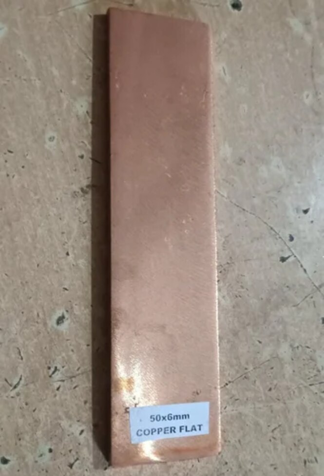
A copper earth electrode plate gives fault current a conductive route from equipment, through the earthing conductor, and into the surrounding soil. To use one correctly, you must understand the installation sequence, specify the plate and connection accurately, and verify that the completed electrode meets the project’s earthing and testing requirements.
Key takeaways
- Bury the copper plate vertically with soil contact on both broad faces.
- Keep the earth electrode, test link and inspection chamber accessible for testing.
- Use a listed jointing method to connect the conductor securely to the plate.
- Compare copper with galvanized steel against soil chemistry and corrosion risk.
How fault current reaches the soil through a copper plate
A copper earth electrode plate gives fault current a conductive surface through which it leaves the earthing conductor and spreads into the surrounding soil. It is the earth electrode—the buried conductive part—not the complete earthing system.
During insulation failure, a live conductor touches exposed metalwork. Current travels from that metalwork along the protective bonding and earthing conductor, through the plate-to-conductor joint, across the copper plate and into the soil.
The soil carries it towards the source’s earthed neutral or grounding point, completing the fault loop so the protective device can disconnect the supply.
The plate does not absorb or destroy fault current. It provides a low-impedance path into the ground for fault, lightning or functional current, while the complete result depends on soil resistivity, electrode geometry, bonding and the required disconnection time.
Check three separate performance points:
- The earthing conductor and plate must withstand the prospective fault current for the protection-clearing time. Designers commonly verify this with the adiabatic conductor-sizing method.
- The connector must remain mechanically tight and resist corrosion. A sound plate with a loose or corroded joint leaves the fault path ineffective.
- The electrode-to-soil resistance must suit the system design. A larger or thicker plate does not guarantee a low value because soil resistivity and moisture usually dominate.
Do not treat copper-clad steel as solid copper. Its steel core and bonded copper layer have different mechanical, corrosion and fault-current characteristics that require product and approval checks.
Installing the plate from excavation to inspection access
Put the plate vertically, with its upper edge at least about 1 metre below finished ground level. This traditional plate orientation reaches more stable moisture and reduces damage from routine digging; confirm the required depth against local rules and ground conditions.
1. Mark the location after checking underground services, then carry out the excavation to provide working space around the plate and the required burial depth.
2. Lower the plate into the excavation without bending or scraping it. Keep it upright and separate from building steel, pipes and other buried metal unless the design specifically bonds them.
3. Attach the earthing conductor using the specified lug, clamp or bolted joint. Tighten it against loosening, protect the connection from corrosion, and route the conductor upward without sharp bends that could damage its insulation or joint.
4. Place approved backfill material evenly around the plate, removing large stones and compacting each layer to eliminate air gaps. Do not treat salt or charcoal as automatic requirements: salt can accelerate corrosion, and moisture-dependent compounds can lose performance after drying.
5. Bring the conductor to a test link or accessible termination, then install a durable inspection chamber at finished ground level. The chamber must allow the joint or test link to be opened for resistance testing without excavating the buried plate.
Record the plate dimensions, conductor size, joint method and burial depth before closing the excavation. Complete the earthing plate installation with a continuity check and earth-resistance test; a sound-looking plate cannot prove that the soil and connection provide the required path.
The plate, earth pit, test link and inspection chamber are different parts
The copper plate is the earth electrode; the earth pit, earthing conductor, test link and inspection chamber serve different functions around it. Confusing these parts can leave you inspecting a cover while the actual connection remains inaccessible.
| Part | What it is used for | What you inspect or test |
|---|---|---|
| Copper plate | Buried metal electrode that transfers current into the soil | Plate condition, dimensions, corrosion and the connected joint |
| Earth pit | Excavated location containing the plate and conductive backfill | Burial depth, backfill condition, water ingress and conductor routing |
| Earthing conductor | Cable or strip carrying current from the installation to the plate | Size, continuity, mechanical damage and termination security |
| Test link | Removable connection between the earthing conductor and electrode lead | Whether the electrode can be isolated for a resistance test, then securely reconnected |
| Inspection chamber | Removable-access enclosure at ground level over the connection area | Joint condition, test-link position, labels, tightening and physical protection |
The earth pit is not the electrode, and the inspection chamber is not the pit. A chamber gives you access to the test link and connection without reopening the excavation; a sealed or buried joint defeats that purpose.
To measure earth electrode resistance, use a fall-of-potential test with auxiliary current and potential electrodes, isolating the test electrode where the procedure requires it. A clamp-on tester normally measures a complete return loop, so parallel bonds can make its reading misleading and cannot prove the resistance of a solitary plate.
Record the test arrangement and result.
Choosing dimensions, copper grade and the plate-to-conductor joint
Do not approve a plate described only as “copper.” Ask for a material declaration naming the copper grade, plate length and width, plate thickness, and whether it is solid copper or copper-clad steel.
A commonly specified British plate is 600 mm × 600 mm and 3.15 mm thick under BS 7430 practice, but those figures are not a universal IEC requirement; confirm the dimensions required by your national installation rules.
Check the purchase drawing and connection details for:
- The hole or lug arrangement, hole diameter, bolt material, washer type and tightening torque.
- The conductor size, termination method and prospective fault current for the protection-clearing time. Confirm thermal adequacy using the applicable wiring standard’s adiabatic calculation; soil-contact resistance alone does not prove fault-current capacity.
- A connector or joint rated for the installation environment and current, with mechanical restraint against loosening and a specified corrosion-protection method.
- Inspection evidence: material certificate, dimensional report, joint photographs or test records, and the installer’s continuity and earth-resistance results.
| Option | What it means | Evidence to confirm |
|---|---|---|
| Solid copper plate | The electrode and connection base are copper | Named copper grade, thickness and dimensions |
| Copper-clad steel | A steel core carries a bonded copper layer | Cladding thickness, bond quality, approval and fault-current rating |
| Copper-to-galvanized-steel transition | Dissimilar metals meet in one earthing path | Listed bimetallic connector or a detail accepted by the governing standard |
S.V. Metals & Extrusions Pvt. Ltd. can be asked to state the lug material, inspection-hole arrangement and conductor range on the supply drawing rather than leaving those choices to site fitting. Never bury a copper-to-galvanized-steel overlap without the specified transition detail; wet, conductive soil can rapidly attack the zinc coating.
Copper versus galvanized steel in real soil conditions
Copper is preferable when an aggressive soil, high moisture, or saline soil would consume the zinc coating on a galvanized steel earthing plate before the installation’s intended service life. It is not automatically the better choice: confirm soil resistivity, chemical conditions, design current and the governing earthing standard before selecting the electrode.
| Option | What it means | When it applies |
|---|---|---|
| Copper plate | Solid copper electrode with strong corrosion resistance in many wet soils | Use where long service life and stable electrode material justify its cost |
| Galvanized steel plate | Zinc-coated steel electrode; the coating protects the steel until it is damaged or consumed | Use where soil chemistry, coating thickness and maintenance access support the design |
| Copper-clad steel | Steel core with a bonded copper layer, not a solid copper plate | Use only when its mechanical, corrosion and approval data match the design |
Never bury copper directly against galvanized steel. In wet or chemically conductive ground, galvanic corrosion attacks the zinc-coated steel; use a listed bimetallic connector or a connection detail accepted by the governing standard.
Verify the completed system by checking the plate, conductor joint, test link and accessible chamber for mechanical security and corrosion protection. Measure electrode resistance with a fall-of-potential test, recording probe spacing, weather and soil conditions. Then confirm continuity of the protective conductor and measure earth fault-loop impedance where required.
Compare the results with the protective device’s disconnection requirement. Separately verify that the plate, joint and conductor withstand the prospective fault current for the clearing time.
Frequently asked questions
How does fault current reach the soil through a copper earth electrode plate?
Fault current travels down the earthing conductor, crosses the plate-to-conductor joint, enters the copper plate and spreads through the surrounding soil.
What parts make up an earthing installation?
The buried copper plate is the earth electrode. The earth pit contains the electrode and backfill, the test link permits measurement, and the inspection chamber provides access.
How do you install a copper earth electrode plate?
Excavate the pit, place the plate with adequate soil contact, connect the earthing conductor, protect the joint, install inspection access and test the completed installation.
How should you choose between copper and galvanized steel?
Compare soil chemistry, moisture, corrosion exposure, required dimensions, conductor compatibility and the expected service life before selecting either material.