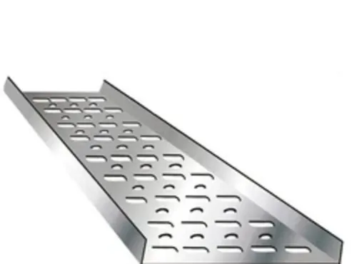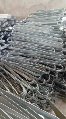
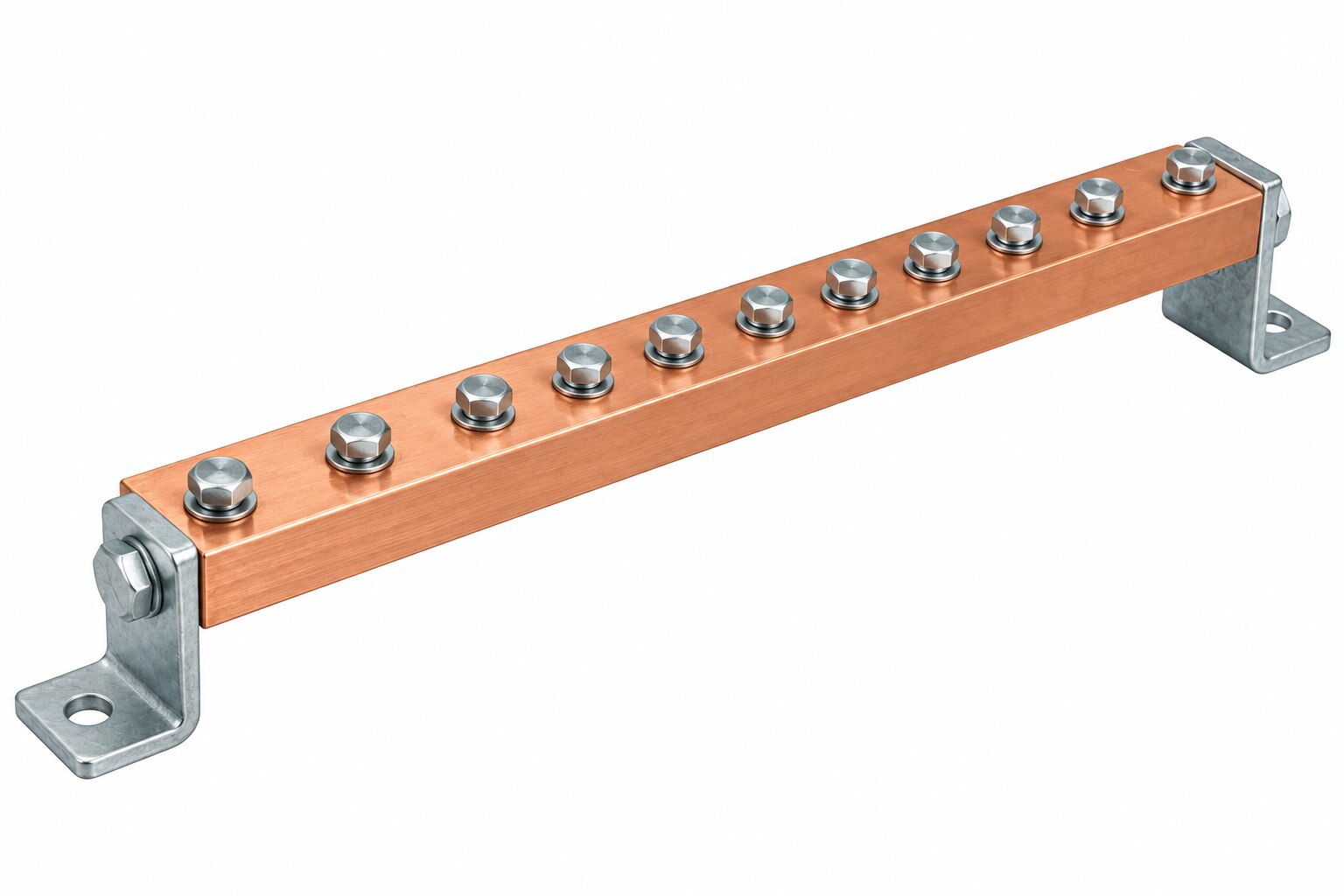
A grounding strip only improves safety when it forms a permanent, low-impedance path from exposed metalwork to the earthing system and allows the protective device to disconnect a fault quickly. By the end, you will be able to trace that path, judge a strip specification, compare materials and identify installation defects that can leave dangerous voltage on equipment.
Key takeaways
- Provide a low-impedance path so protective devices receive enough fault current.
- Route the strip from equipment earth terminals to the main earthing terminal.
- Size the strip for prospective fault current, duration and mechanical conditions.
- Inspect joints, corrosion, continuity and connections throughout the installation.
How the strip clears an insulation fault
When a live conductor touches a metal enclosure, the grounding strip provides a low-impedance fault current path from that enclosure through the protective bonding network to the main earthing terminal and grounding electrode system. The resulting current gives the fuse, circuit breaker or other protective device enough magnitude to disconnect the faulty circuit.
The strip does not detect the fault or trip the breaker. It supports protective device operation by keeping fault-loop impedance low and carrying prospective fault current for the required disconnection time.
A strip that passes a simple resistance test can still be too small for the short-circuit duty; thermal sizing may require the adiabatic check S = I√t/k.
Paint, powder coating, rust and scale at a lug can interrupt this path. Prepare the contact surfaces for an approved metal-to-metal joint, then protect the surrounding joint without coating the intended contact area.
The strip differs from other earthing components in its position and job:
- Grounding strip: a robust conductor used to bond equipment and interconnect parts of the earthing network.
- Grounding electrode conductor: the conductor connecting the main earthing terminal or bar to an electrode system.
- Bonding jumper: a flexible or short conductor bridging a removable joint, door, flange or separate metal section.
- Earth electrode: a rod, plate, grid or buried metalwork that transfers current into the surrounding soil.
A strip alone proves nothing; safety depends on the complete, permanent path and correct disconnection.
The route from equipment earth terminals to the electrode system
The route should form a continuous, low-impedance path: equipment earth terminal to the grounding strip, strip to the main earthing bar, and main earthing bar to the earth electrode system. Keep the run as short and direct as the layout permits; sharp bends add impedance and create weak points.
- Bond every exposed metal enclosure, machine frame and cable-tray section to the strip at its designated earth terminal. Use a bonding jumper where the strip cannot connect directly, such as across a flexible coupling, hinged door or removable section.
- Route the strip to the main earthing bar without passing through a switch, fuse or disconnect link. Support exposed runs against vibration and protect them from forklifts, impact, heat and corrosive chemicals.
- Connect the main earthing bar to the earth electrode system with a grounding electrode conductor. Terminate it at the specified earth pit or rod connection, or at another electrode designed for the installation.
- Keep joints accessible for inspection where practical. Use prepared metal-to-metal contact surfaces, correct washers and tightening torque; remove paint, powder coating, rust and scale from the contact area, then protect the joint without covering that electrical interface.
- Provide a labelled test link or accessible disconnecting point where the design requires electrode testing. Do not bury an improvised clamp or leave a joint inaccessible.
An earth-resistance reading alone cannot prove this route is continuous. Commissioning should check strip continuity, bonding-jumper connections, structural-steel bonds and the protective device’s required disconnection condition. Parallel routes through steelwork or cable trays also need coordination with EMC and stray-current controls.
How to size and configure a strip for fault duty
Size the strip from the worst credible fault current and clearing time, not from width alone. Confirm the protective device will disconnect within the required time and that the complete path has suitably low impedance.
- Electrical: use the prospective short-circuit or earth-fault current at the installation point, including parallel paths, transformer data and protective-device coordination.
- Thermal: apply the adiabatic relationship S = I√t/k. Here, S is cross-sectional area, I is fault current, t is disconnection time and k reflects the metal, insulation and permitted temperature. A low resistance reading does not prove adequate fault-duty capacity.
- Mechanical: check span, support spacing, vibration, forklift impact, thermal movement, bending and the strength of bolted joints.
- Layout: minimise unnecessary bends and joints, provide accessible test points, protect exposed runs, and coordinate the strip with equipment bonds, structural steel and the main earthing bar.
| Check | Evidence required | Design consequence |
|---|---|---|
| Fault duty | Short-circuit study and protection settings | Set area for the highest current and clearing time |
| Soil and electrode system | Soil-resistivity report, burial depth and earthing layout | Confirm the installed geometry; catalogue resistance values do not transfer between sites |
| Environment | Corrosion assessment and mechanical-risk review | Select protection, supports and joint details for the location |
Use IS 3043 and IEC 60364-5-54 as the principal design references, together with the approved single-line diagram, earthing layout, equipment fault ratings, protection-coordination study and project specification. Where requirements differ, resolve them before fabrication and record the adopted basis.
Choosing metal and protecting it in service
Choose a metal for the soil, interfaces and physical exposure, not conductivity alone. Record pH, chlorides, sulfates, moisture variation and stray direct-current sources before selecting an underground strip; these conditions can accelerate electrolytic attack.
| Metal | Choose it when | Main risk or control |
|---|---|---|
| Galvanized steel strip | Cost, mechanical strength and moderate soil exposure matter | Scratches, cut ends and welds expose steel; repair approved damaged areas with a compatible zinc system, or replace severely attacked sections |
| Copper strip | Soil is corrosive to zinc and steel, and copper-compatible connections are available | Copper joined directly to galvanized steel in wet conditions creates galvanic corrosion; use an engineered transition and seal the interface |
| Copper-clad steel | You need steel’s strength with a copper corrosion barrier, especially for driven or mechanically exposed sections | Do not cut, file or crush the copper layer; exposed steel at damaged ends needs approved treatment |
| Bare steel | The design includes corrosion allowance, inspection or planned replacement in a low-corrosion environment | Rust can reduce cross-section and loosen joints; do not bury it without a documented soil-life assessment |
| Stainless steel | Chemical exposure or persistent wetness rules out galvanized steel and copper | Specify a grade suited to chlorides and avoid dissimilar-metal contact without isolation or a rated connector |
A damaged galvanized earthing strip is not “still protected” because most of its surface looks bright. Inspect bends, clamps, welds and buried transitions; paint, rust or scale at equipment lugs must be removed only at the contact area, then the finished joint protected without insulating that interface.
If S.V. Metals & Extrusions Pvt. Ltd. supplies the strip, give the purchase specification the soil report, joint metals, coating-repair method and exposure zone.
Related product
 | Earthing Galvanized Earthing Strip View product → |
Inspecting, testing and preserving the fault-current path
A low earth-electrode resistance reading does not prove that every protective-bonding connection is intact. Inspect the complete fault-current route from equipment earth terminals through the strip, main earthing terminal and electrode connections; a loose joint can leave remote-earth measurements unchanged while preventing rapid protective-device operation.
Use this inspection checklist after installation and after nearby construction, equipment moves or cable-tray alterations:
- Examine bolted joints for correct hardware, tightness, clean contact surfaces, corrosion, paint between mating faces and signs of overheating.
- Confirm bonds from the strip to equipment enclosures, cable trays, structural steel, doors, gates and removable covers.
- Check supports, clamps and protective guards for looseness, sharp edges, vibration damage and contact with chemicals or vehicles.
- Trace exposed runs for cuts, unauthorized removal, damaged galvanizing, excessive bends and missing identification.
- Confirm accessible test links remain reachable, labelled and closed after testing.
Continuity testing with a suitable low-resistance instrument checks for open circuits across joints and between bonded metalwork. Low-impedance testing then assesses the complete fault path; compare readings with the design limit and investigate unexpected changes rather than accepting a single pass result.
Finish by measuring prospective fault current or earth-fault loop impedance at representative equipment and confirming that each protective device meets its specified disconnection condition. Record test points, readings, instrument details and repairs. Re-test any joint disturbed by construction, even when the original commissioning certificate is available.
Frequently asked questions
How does a grounding strip clear an insulation fault?
It carries fault current from a live conductor touching a metal enclosure through the protective bonding network to the main earthing terminal and electrode system. The resulting current helps a fuse or circuit breaker disconnect the circuit.
Where does the grounding strip connect in an industrial installation?
The route runs from equipment earth terminals through bonding conductors or strips to the main earthing terminal, then to the grounding electrode system.
What factors determine grounding strip size?
Choose the cross-sectional area and configuration for the prospective fault current, fault-clearing time, installation conditions and mechanical protection required.
What should you inspect on a grounding strip?
Check continuity, bolted or welded joints, connection tightness, corrosion, physical damage and the strip’s connection to the main earthing and electrode systems.