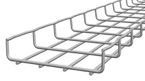
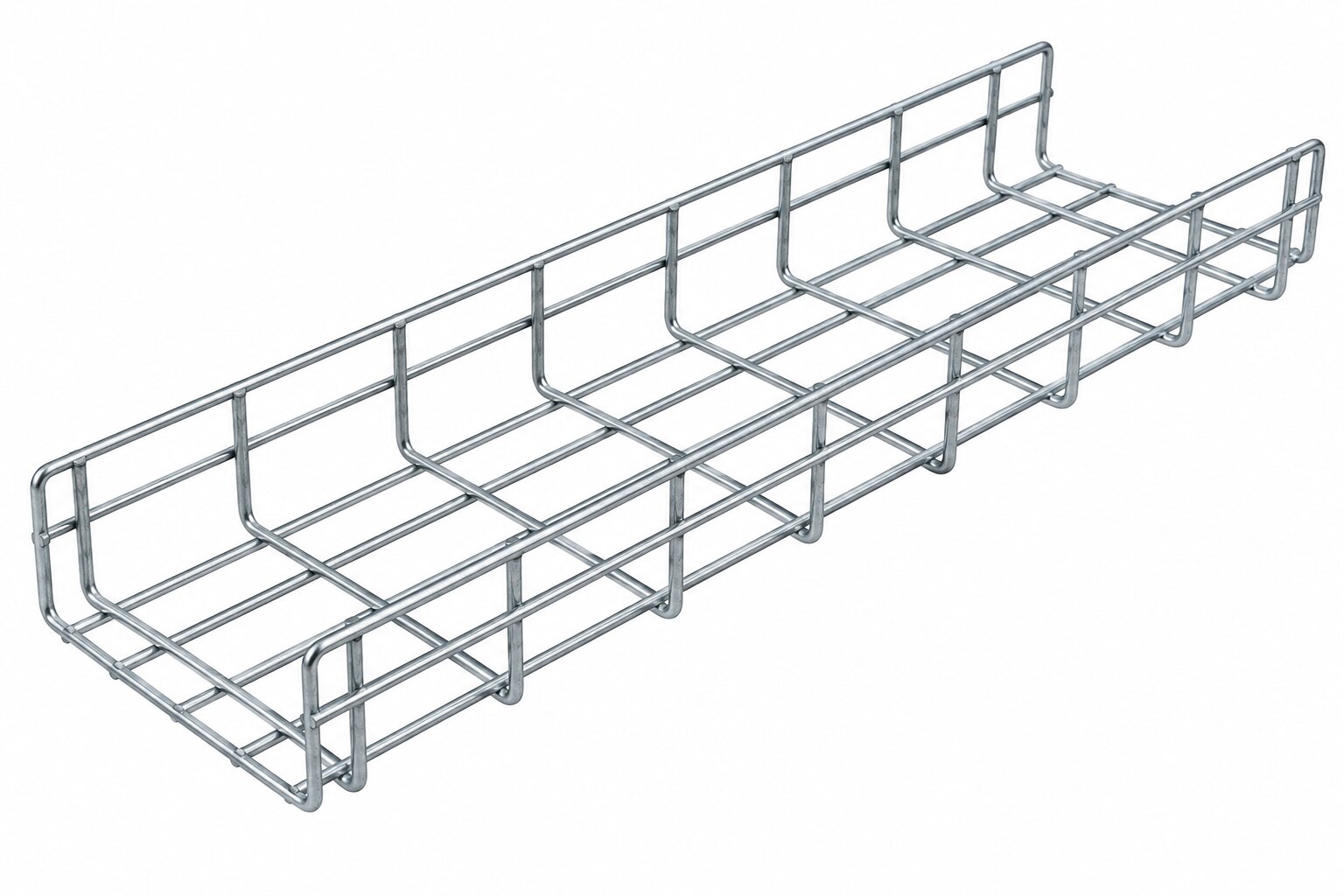
A zinc-plated wire mesh tray can make cables visible, reachable and easier to rearrange, but only when its coating, structural capacity, route and internal organization match the installation. You will be able to compare the finish, size the tray, separate cable systems and check whether the completed route remains safe to inspect and maintain.
Key takeaways
- Confirm electrogalvanized or hot-dip galvanized zinc before approving the tray.
- Allow space for cables, supports, bend radii and difficult route sections.
- Use open mesh access while maintaining separation and bend control.
- Complete bonding, firestopping and an access check before handover.
Confirm What “Zinc Plated” Means Before You Specify the Tray
A quotation that says only “zinc plated” does not tell you whether a zinc plated wire mesh tray will survive its location. Ask whether the finish is electrogalvanized zinc or hot-dip galvanized zinc: the processes produce different coating thicknesses and outdoor durability, while zinc protects the substrate steel through sacrificial corrosion.
1. Request the coating standard, zinc coating mass or thickness, and the substrate steel grade. For comparison, ask whether ISO 1461 or ASTM A123/A123M applies to hot-dip galvanized parts, and whether the supplier uses a stated electrogalvanizing standard such as ASTM A879/A879M.
2. Match that coating specification to the exposure. Coastal air, chemical fumes, continuously wet areas, buried routes and washdown zones need more than an indoor zinc finish; ask for the stated corrosion category or service environment.
3. Inspect a sample and the delivery documents for coating coverage at welds, bends, splice areas, drilled holes and cut ends. White rust shows zinc oxidation; red rust means the underlying steel is corroding.
4. Confirm how field damage will be repaired. For hot-dip galvanized coatings, ASTM A780 describes repair methods; require surface preparation and a specified zinc-rich repair system instead of unprepared paint.
5. Check galvanic contact with aluminium or stainless steel, where moisture can accelerate attack at the interface. A zinc finish that suits a dry plant room is not automatically suitable for marine or chemical service.
Size the Mesh Tray Around Cables, Supports and Difficult Route Sections
Choose width from the actual cable outside diameter, not a generic cable tray fill percentage. Add the diameters of the cables, separation required between power, control, data and fibre circuits, and spare capacity for planned additions. NEC Article 392 uses cable type and arrangement, so the 40% conduit-fill rule is not a safe substitute.
| Option | What it solves | When it applies |
|---|---|---|
| Hold-downs or ties | Stops small cables dropping through openings or lifting at turns | Flexible, single-core or vertically routed cables |
| Divider bars | Maintains circuit separation | Power beside control, instrumentation or communications cables |
| Smaller-opening or solid-bottom section | Prevents sagging and escape | Small cables, risers, transitions and tight bends |
| Firestop system | Preserves a rated wall or floor penetration | Where the route crosses a fire-rated barrier |
Set tray depth from the largest cable, its bend requirement and the fixing method; a shallow tray that forces a tight bend damages the cable. Check the manufacturer’s tray load rating at your planned support span, width, splice position and any concentrated load.
IEC 61537 and NEMA VE 1 provide the testing framework, but the published load table controls.
Fix supports to the tested spacing rather than transferring a kilograms-per-metre figure from another tray. At every turn, riser, wall penetration and cut end, add the specified bracket, divider, hold-down or edge protection; a structurally adequate tray can still damage or release cables.
Provide a compatible listed firestop that allows approved future additions without losing the rating.
Use Open Access Without Losing Cable Separation or Bend Control
Open mesh gives you cable accessibility: you can inspect labels, check supports, and lift a cable into or out of a side section without threading it through a closed duct. That advantage disappears when the tray is tightly packed, fixed against a wall, buried above pipework, or blocked by continuous lids.
Plan cable segregation before installation; physical space alone does not make mixed circuits suitable. Use the separation method required by voltage, electromagnetic compatibility, shielding and the applicable electrical or communications standard:
- Power cables: use a separate tray, metallic divider or specified spacing from sensitive circuits.
- Control and instrumentation cables: keep them away from sources of interference and follow the control-system wiring rules.
- Data cables: preserve their separation, shielding arrangement and manufacturer’s routing limits.
- Fibre cables: protect them from crushing, sharp edges and tight turns, even though they do not carry electrical interference.
At every horizontal or vertical change of direction, follow the cable manufacturer’s minimum bend radius, pulling tension and sidewall-pressure limits. The tray’s curve does not set those limits. Small cables can fall through large openings or sag between supports, so use hold-downs, divider bars, cable cleats and ties where the route needs restraint.
Reserve side and vertical working clearance for additions and fault-finding, and protect cut mesh ends so maintenance work does not damage insulation. Open mesh also improves heat dissipation, but grouped-cable ampacity still requires the specified derating for load, ambient temperature and installation arrangement.
Match Zinc-Plated Mesh to the Environment and the Job
Zinc-plated mesh is the better choice for an indoor or covered route where corrosion exposure is moderate and you need ventilation, visual access and quick cable entry. It is not a safe default for chloride spray, chemical vapour, continuous wetting, burial or washdown.
Trapped moisture at joints and galvanic contact with aluminium or stainless steel can accelerate failure.
| Option | Choose zinc-plated mesh when | Choose the alternative when |
|---|---|---|
| Stainless-steel mesh tray | The route is dry, sheltered and cost-sensitive | Chlorides, chemicals or persistent moisture demand stronger corrosion resistance |
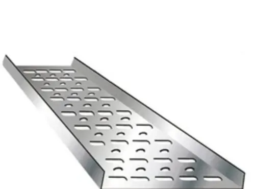
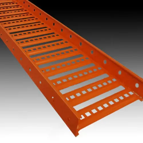
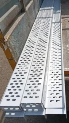
| Perforated cable tray | You need open inspection and ventilation with flexible cable entry | Small cables need continuous support, or debris and dripping water must be contained |
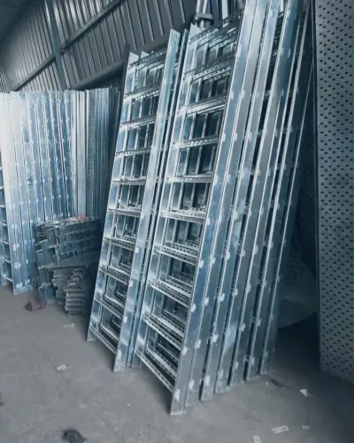
| Ladder tray | Cables are moderate in size and require frequent access | Heavy power cables need wide support, restraint or long-span strength |
| Conduit versus cable tray | Many cables share an accessible route and heat dissipation matters | Each cable needs enclosed mechanical protection, separation or a sealed penetration |
| Solid-bottom tray | You need a short transition section or support for small cables | The route benefits from drainage, airflow and easy visual inspection |
A zinc finish protects the steel sacrificially, but a scratch or cut edge can develop white rust first and red rust later. Specify electrogalvanized or hot-dip galvanized steel, coating designation, thickness or mass, substrate and environment; do not accept “zinc plated” alone.
For small, flexible or single-core cables, add hold-downs, divider bars, ties or smaller mesh. Use solid-bottom sections at risers and turns when cables sag or drop through openings. S.V. Metals & Extrusions Pvt. Ltd. can be asked to identify those accessories and the coating specification on the quotation.
Related products
 | Cable Trays & Accessories Wire Mesh Cable Tray, also called Basket Cable Tray, is a kind of cable tray made of stainless steel wires by welding wires together, forming a... View product → |
 | Cable Trays & Accessories Wire Mesh Cable Tray Accessories Wire Mesh Cable Tray Accessories View product → |
Finish the Installation With Bonding, Firestopping and an Access Check
Before handover, verify three outcomes: the metallic route is electrically continuous, each penetration retains its fire rating, and technicians can reach the cables without dismantling other services.
- Inspect every splice, bend, tee, reducer, lid and support for tight fasteners, burr-free edges and approved bonding jumpers. Coated, painted, corroded or dissimilar-metal joints do not automatically provide a reliable protective path.
- Confirm the protective bonding conductor is correctly sized, securely terminated and connected to the site earthing system at the points shown on the drawings. Check that removable tray sections have bonding jumpers where the design requires them.
- Perform a cable tray continuity test across the complete installed route, including joints and jumpers. Record test points, results and the instrument used; investigate any open circuit before cables are energised.
- Examine every wall and floor penetration for a listed, compatible firestop system. The seal must suit the tray, cable types and future additions while preserving the required fire-resistance rating.
- Walk the route with the access panels open. Confirm a technician can lift cables from the mesh, operate tools and add a cable without removing pipework, lighting, ductwork or neighbouring services.
- Check cable bend radii, separation, tie locations and protection from sharp cut ends. Replace damaged cables and fit edge protection where metal could abrade insulation.
- Recheck grouped-cable loading against the specified ampacity method. Open mesh improves airflow, but conductor loading, ambient temperature and cable arrangement still control derating.
Frequently asked questions
What does “zinc plated” mean on a wire mesh tray?
Confirm whether the tray is electrogalvanized or hot-dip galvanized. The processes create different coating thicknesses and levels of outdoor durability.
How do you size a wire mesh tray for cable routes?
Allow room for the cable bundle, supports, required bend radii and difficult sections such as bends, risers and route changes.
How can open mesh improve cable management without damaging cables?
Use the access provided by the mesh for inspection and additions, while preserving cable separation, support and each cable’s minimum bend radius.
What must be checked before completing a mesh tray installation?
Check bonding continuity, firestopping where the route crosses barriers, cable support and access for inspection or future additions.